555 Timer Internal Schematic / A Plethora Of Ne 555 Data Ne555 Tutorials Page : Today we're going to discuss about 555 timer ic or ne555.. The image shown below represents the internal schematic of a standard ic 555. In this video, i've explained 555 timer ic with the pin diagram and the internal circuit diagram. Nov 11, 2009 #1 jearls74. 555 timer internal circuit diagram. Its name is derived from three 5k ohm resistors ,connected in series used in it.the timer ic can produce required waveform accurately.
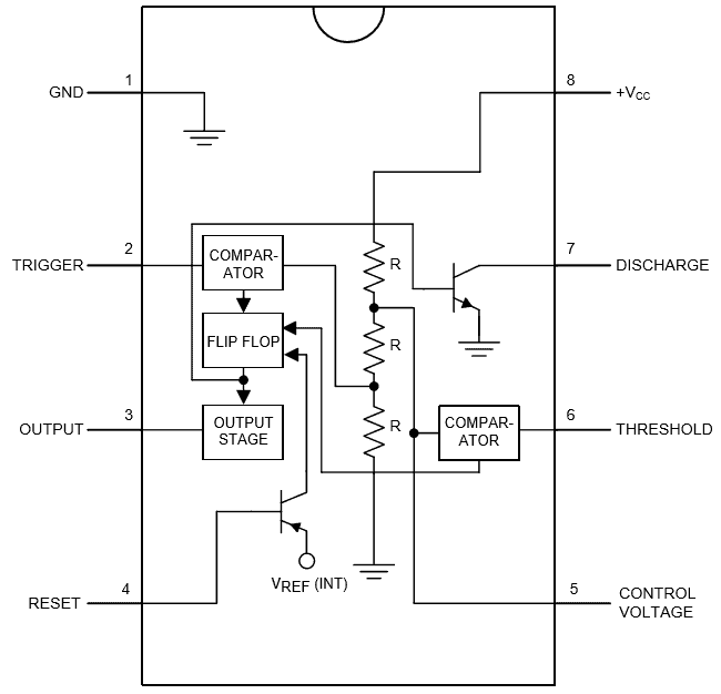
We can see that it us made up of 21 transistors, 4 diodes, and 15 resistors. The three resistors used in it are of 5kohm and they served as a voltage divider between vcc and ground. We have seen in the last few tutorials that the 555 timer can be configured with externally connected components as multivibrators, oscillators and timers, with timing intervals ranging from a few microseconds to many hours. In this article, we cover the following information about 555 timer ic. 555 timer internal circuit diagram.
555 Timer Ic Types Construction Working Applications from www.electricaltechnology.org Ic 555 timer is a one of. In this article, we cover the following information about 555 timer ic. Ic 7555 is the cmos version of the 555 ic with same pin configuration and function. Unlike monostable multivibrator mode it doesn't have any stable state, it has two quasi stable state (high and low). In 2017, it was said over a billion 555 timers are produced. As its wide range of usability and compatibility, also its more range of operating voltage and various other feature makes it ideal for wider use. The circuit latches in either the q state or its refer block diagram of 555 timer ic given above: In this section, we will see the working of each internal component of the 555 timer ic.
No external triggering is required in astable mode, it automatically interchange its two states on a particular interval, hence generates a rectangular waveform.
You may already know that se/ne 555 is a timer ic introduced by signetics corporation in 1970's. In this circuit, we have four basic blocks, these are 1. The 555 timer has two basic operational modes: For explaining the operation of timer 555 as a monostable multivibrator, necessary internal circuitry with external connections are shown in figure. Start date nov 11, 2009; The internal block diagram and schematic of the 555 timer are highlighted with the same color across all three drawings to clarify how the chip is implemented:2. Ic 555 timer is a one of. We have seen in the last few tutorials that the 555 timer can be configured with externally connected components as multivibrators, oscillators and timers, with timing intervals ranging from a few microseconds to many hours. The image shown below represents the internal schematic of a standard ic 555. It is available in 3 different packages: You can find here some circuits based on 5555 ic. The voltage must be at least 4.5v and no greater than 15v. 555 timer internal circuit diagram.
We have seen in the last few tutorials that the 555 timer can be configured with externally connected components as multivibrators, oscillators and timers, with timing intervals ranging from a few microseconds to many hours. Basic 555 monostable multivibrator circuit. The timer's internal circuitry is largely responsible for this triggering but it is also caused stray or installed capacitance at the trigger input of the timer. 555 timer internal schematic questions thread starter jearls74; Inside the 555 chip, three resistors form a divider generating reference voltages of 1/3 and 2/3 of the supply voltage.
How Does A Ic 555 Operate Quora from qph.fs.quoracdn.net 555 internal circuit consists of three series 5k resistors connected between the vcc and gnd. 555 timer was first introduced by signetics corporation in 1971 as se555/ne555. Inside the 555 chip, three resistors form a divider generating reference voltages of 1/3 and 2/3 of the supply voltage. There are a lot of applications of this ic, mostly used as vibrators like, astable multivibrator, monostable multivibrator, and bistable multivibrator. It can operate in both astable and monostable modes. Monostable 555 timer circuits will automatically trigger and start a timing cycle when power is applied to the circuit. Ic 7555 is the cmos version of the 555 ic with same pin configuration and function. Internal diagram of 555 timer ic.
In 2017, it was said over a billion 555 timers are produced.
In this video, i've explained 555 timer ic with the pin diagram and the internal circuit diagram. Hi everyone, i am trying to build a very high current dc to ac inverter and i cant use a 555 timer ic because they cant source or sink but a maximum of 200ma, but i have found an internal schematic of the 555 timer ic online. The ic 556 and ic 558 are 14 pins dual timer and 16 pin quad timer versions of the ic 555 respectively. Its name is derived from three 5k ohm resistors ,connected in series used in it.the timer ic can produce required waveform accurately. Monostable 555 timer circuits will automatically trigger and start a timing cycle when power is applied to the circuit. This tutorial covers different aspects of 555 timer ic and explains its working in The working modes of a 555 timer are astable, bistable, and monostable. Inside the 555 chip, three resistors form a divider generating reference voltages of 1/3 and 2/3 of the supply voltage. We have seen in the last few tutorials that the 555 timer can be configured with externally connected components as multivibrators, oscillators and timers, with timing intervals ranging from a few microseconds to many hours. The diagram below illustrates the internal operation of the 555 timer used as an oscillator. The 555 timer has two basic operational modes: An external capacitor is repeatedly charged and discharged to produce the oscillation. This is the pin which connects to the dc voltage to power the 555 chip.
Ic 7555 is the cmos version of the 555 ic with same pin configuration and function. Pcs, handys, zubehör & mehr Hi everyone, i am trying to build a very high current dc to ac inverter and i cant use a 555 timer ic because they cant source or sink but a maximum of 200ma, but i have found an internal schematic of the 555 timer ic online. Jetzt timer 555 angebote durchstöbern & online kaufen. 555 timer internal schematic questions thread starter jearls74;
What Is The Meaning Of Ic 555 Quora from qph.fs.quoracdn.net The standard 555 timer ic is made of 2 diodes. Hi everyone, i am trying to build a very high current dc to ac inverter and i cant use a 555 timer ic because they cant source or sink but a maximum of 200ma, but i have found an internal schematic of the 555 timer ic online. The 555 is also very versatile, and can be used. The voltage must be at least 4.5v and no greater than 15v. Jetzt timer 555 angebote durchstöbern & online kaufen. The 555 timer internal circuit diagram is shown below: In 2017, it was said over a billion 555 timers are produced. Ic 555 timer is a one of.
In this article, we cover the following information about 555 timer ic.
Pcs, handys, zubehör & mehr Simple 555 timer circuits & projects. The 555 timer can be operated at a wide range of power supplies ranging from 5 v to 18 v. Lm555 timer 1 features 3 description the lm555 is a highly stable device for generating 1• direct replacement for se555/ne555 accurate time delays or oscillation. The internal block diagram and schematic of the 555 timer are highlighted with the same color across all three drawings to clarify how the chip is implemented:2. In this circuit, we have four basic blocks, these are 1. In 2017, it was said over a billion 555 timers are produced. This tutorial provides sample circuits to set up a 555 timer in monostable, astable, and bistable modes as well as an in depth discussion of wiring info: If a 10uf timing capacitor is used, calculate the value of the resistor required to produce a minimum output time delay of 500ms. The second 555 timer helper will extend the timers output duration without having to use large values of r1 and/or c1. As its wide range of usability and compatibility, also its more range of operating voltage and various other feature makes it ideal for wider use. A monostable 555 timer is required to produce a time delay within a circuit. The working modes of a 555 timer are astable, bistable, and monostable.
In this article, we cover the following information about 555 timer ic 555 timer schematic. 555 timer internal circuit operation.


0 Komentar